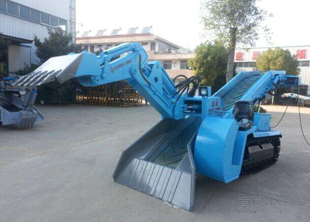

What do you know as a mini mucking loader? Don't be afraid that the billion-million mini mucking loader manufacturers have made some explanations about the use of switches for novices. Let's learn together.
1. The hydraulic system of the mini mucking loader drive system has overload protection function. When used, the system pressure must not exceed the design pressure.
2. There are two operating handles on the console. The front and rear directions of the right handle control the forward and backward movement of the trolley, and the left and right direction controls the tilting movement of the slag arm up and down. The left and right handles control the slag plate to be lowered and lifted, and the left and right direction control frame swings to the left and right. The right handle pushes the front and rear direction to control the proportional valve, which can control the running speed of the trolley according to the pushing angle. The larger the pushing angle is, the faster the speed is. The other handles of the two handles are controlled by the reversing valve. The adjustment is pre-adjusted by the throttle valve in the hydraulic system.
3, mini mucking loader manufacturers walking trolley travel switch set to meet the slag stroke can not let the walking car often hit the spring buffer device; slag arm tilt and slag plate down distance is limited by the maximum stroke of the hydraulic cylinder.
4. The Ф10 pin on the adjusting screw joint on the trolley is a safety pin. When an abnormal situation occurs and the transmission system is forced to exceed the design slag force by 2 to 3 times, the pin will be cut off to protect the hydraulic motor, chain and the like. If the safety pin is cut off, the cause of the accident must be analyzed and the corrective measures must be taken before the original structure can be restored.
5. One limit switch is arranged for swinging left and right of the frame. One control maximum working angle is 10°, and the other control station has a maximum corner angle of 45°. The maintenance station corner can be set according to the actual needs of the work site.
6. There is a limit switch at the front end of the rack. After the switch is knocked down, the car will automatically stop. Due to the different speed of the operating car, the inertia action will make the car stop distance different. The front travel switch position is generally set to stop the car without hitting the buffer after the medium speed impact. In actual operation, the car does not need to go because of the position limit of the ladle. Front limit position. There are two limit switches at the rear of the rack. The front is a deceleration switch. When it is knocked down, it will output a signal to control the deceleration of the car. When the car hits the rear limit switch, it will stop quickly.
